How to do traditional machining drilling with over 10 million holes and a diameter of 0.1mm?
Addressing the high-precision processing demands in medical devices and biochips, we provideend-to-end micro-nano manufacturing solutions from design to mass production, meeting thestringent precision and cleanliness standards of the medical industry.
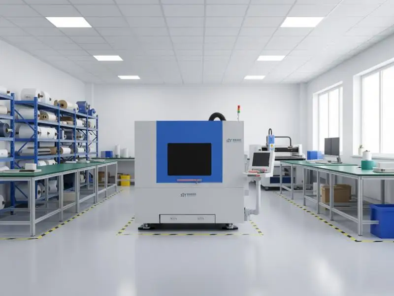
Processing Results
- laser drilling
- laser drilling machine
- laser drilling equipment
- precision laser drilling
- laser micro-hole machining
Details
Professionals working with filter screens, spinnerets, atomizer discs, and flow control plates have all encountered orders like this: customers need tens of millions of micro-holes drilled into a single plate, with a hole diameter of 0.1mm, requiring zero burrs, no deformation, and a 100% penetration rate. This may sound like a domain exclusive to laser drilling, but in many scenarios, traditional machining still offers irreplaceable advantages. This article systematically breaks down the traditional machining approach for such ultra-high-density micro-hole applications from four dimensions: process selection, tooling strategy, workholding methods, and quality inspection.
1. Why Still Consider Traditional Machining?
Laser drilling is fast and highly precise, yet for certain materials and operating conditions, conventional mechanical drilling retains unique value. First is material adaptability — for materials with low laser absorptivity such as titanium alloys and nickel-based superalloys, mechanical drilling delivers more controllable hole-wall quality. Second is hole geometry consistency — the cylindricity and roundness achieved by mechanical drilling are significantly superior to laser drilling when the aspect ratio exceeds 3:1, which is critical for components like spinnerets that require precise flow-channel control.
Furthermore, when batch volumes exceed 5 million parts, the per-hole cost of mechanical drilling continues to decrease as tool life is optimized, whereas depreciation and energy costs for laser equipment remain essentially fixed. For stainless steel 304 and 316L screen substrates with thicknesses of 0.3–0.8mm, the micro-drilling approach often proves more competitive in terms of overall cost.
2. Tooling Strategy: Selecting and Managing 0.1mm Micro-Drills
The 0.1mm diameter micro-drill is the core bottleneck of the entire process. Currently, two mainstream solutions exist: solid carbide micro-drills and PCB-specific micro-drills. The former is suited for metal plates, while the latter performs better on fiberglass and composite materials. For drilling 0.5mm-thick 304 stainless steel, for example, a carbide micro-drill with a 0.1mm diameter, 1.5mm flute length, and 3mm shank diameter is recommended, with a helix angle of 30°–35° and internal coolant channels.
Recommended Cutting Parameters
Spindle speed should be set between 15,000–25,000 rpm, with a feed rate of 0.5–2mm/min, depending on material hardness and plate thickness. The key is to adopt a peck-drilling cycle — retracting the drill after every 0.15–0.2mm of depth to clear chips, preventing chip clogging that leads to tool breakage. Coolant must be delivered via high-pressure through-tool cooling at no less than 30bar, ensuring adequate lubrication at the cutting zone and efficient chip evacuation.
Tool Life and Replacement Strategy
The typical tool life of a 0.1mm micro-drill in stainless steel ranges from 200 to 500 holes. For an order involving tens of millions of holes, this means tens of thousands of tool changes will be required. It is recommended to use an off-machine tool presetter to pre-set tool-length compensation, combined with the machine tool's built-in tool-life management function, which triggers an automatic tool change once the preset hole count is reached. Additionally, 10% of tools from each batch should be sampled for microscopic cutting-edge inspection to build a life-versus-wear curve and dynamically adjust the replacement threshold.
3. Workholding and Positioning: Ensuring Accuracy Across Tens of Millions of Holes
When over 10 million holes are distributed across an entire plate, cumulative error becomes the greatest hidden challenge. The workholding solution must simultaneously address two issues: controlling thermal deformation of the plate during machining, and maintaining positioning accuracy across multiple setup operations.
A vacuum chuck paired with flexible supports is recommended to avoid the localized stress deformation caused by mechanical clamps. For large-area thin plates (e.g., 500mm × 500mm and above), it is advisable to machine a reference grid on the back side of the plate — using a coordinate grinder to pre-machine cross-shaped reference marks at 50mm intervals. All subsequent drilling operations then use these reference points for visual alignment compensation.
Stitch-Machining Strategy
Tens of millions of holes typically require multiple setups, machining the plate zone by zone. At each re-clamping, the machine's CCD vision system identifies the pre-positioned reference marks on the plate, automatically calculates the offset, and compensates the machining coordinate system accordingly. Hole-position overlap in stitch zones should be controlled within ±0.005mm to ensure uniform hole distribution across the entire plate.
4. Quality Inspection: How to Verify Quality Across Tens of Millions of Holes
Traditional full-inspection methods are completely impractical at the scale of tens of millions of holes. The recommended quality-control strategy is divided into three tiers: First-article full inspection — the first plate undergoes comprehensive sampling inspection of all hole positions using a coordinate measuring machine (CMM) or high-precision vision system (at least 25 holes per square centimeter), establishing the process baseline. In-process patrol inspection — every 500,000 holes, sample checks are performed for hole diameter, positional deviation, and burr condition. Final-piece comparison — the last plate is statistically compared against first-article data to confirm process stability.
For hole diameter measurement, pneumatic gauges or laser scanning micrometers are recommended, achieving accuracy of ±0.001mm. Burr inspection requires observation under a 200× microscope to measure the flip-up height at the hole entry and exit, generally required to be no more than 5% of the hole diameter, i.e., 0.005mm.
5. Summary
Traditional machining of over 10 million 0.1mm micro-holes is far from an impossible task, but it demands tooling management, clamping precision, and process discipline that far exceed conventional machining standards. The key takeaways can be summarized as: select the right tools (carbide through-coolant micro-drills), control the parameters (high speed, low feed, plus peck drilling), stabilize the workholding (vacuum chuck + reference grid), and enforce strict quality control (three-tier sampling system). If your project faces similar high-density micro-hole requirements, feel free to contact us for a customized process evaluation.
Need a similar processing solution?
Contact our technical experts for a customized solution
Contact Us: +8618682295530